Simple Light Sensor Circuit Tutorial Circuit Diagram
Simple Light Sensor Circuit Tutorial Circuit Diagram This circuit can be used to automatically control and turn on-off lights or any loads depending on the brightness of ambient light, by adding a relay at the output. The sensitivity a.k.a the brightness at which the circuit switches on the load can also be controlled by using a potentiometer.

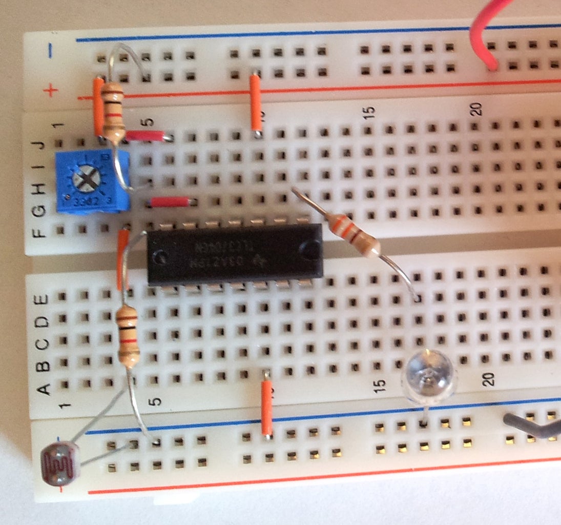
Light Detector Sensor Circuit Diagram: The circuit of light detector is very simple and easy to build with very few components. As you can see in the LDR circuit diagram, it can be a distinguished as two smaller circuits; a) Voltage divider made using LDR (LDR1) and a Potentiometer (RV1) b) Output (LED D1) in our switching circuit made using a Using this circuit, an electrical device or an appliance like a light bulb or a fan for example, can be controlled based on the intensity of the light near the circuit. Principle behind the Circuit The main principle of this circuit is based on the working of the LDR Sensor i.e. the Light Dependent Resistor and to switch ON or OFF the light

Light Detector Sensor: Building a Simple Circuit Circuit Diagram
This Arduino Light sensor circuit is a simple example that shows you how to connect light sensors such as photoresistors, photodiodes, and phototransistors, to an Arduino. In this quickstart guide, you'll learn how to connect a photoresistor to an Arduino board and read out the voltage. You'll first use the Serial Monitor to learn about how
The 330K Ohm Resistor and LED can be replaced with virtually anything to trigger a signal or an event. For example, a 9 Volts Relay would be used to make an absence-of-light activated switch. To make this circuit operate in reverse (the LED turns on when there is light), simply just exchange the positions of the Variable Resistor and the LDR.

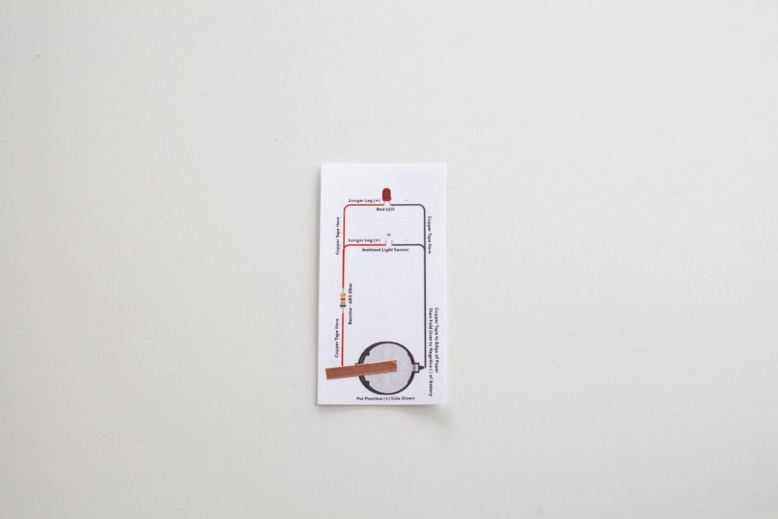
DIY Light Sensor Circuit: Step Circuit Diagram
When sufficient light shines on the LDR, it turns off. Light Circuit Diagram: Reverse R2 and LDR to detect light or dark. Light Sensor Circuit Explanation. As light shines on the LDR, its electrical resistance is lowered from the multiple MOhm range in total darkness to the 100 Ohm range with sufficient light. The LDR and R2 act as voltage Variable resistor VR 1 is used to adjust the sensitivity of LDR i.e., on what intensity of light, the circuit triggers the load (LED). Another input voltage is taken from the voltage divider network using resistor R1 and R2 which forms a voltage divider network that divides Vcc into two parts thus ½ Vcc volt is available at inverting input.